 Daniel
 deutsche Version anzeigen
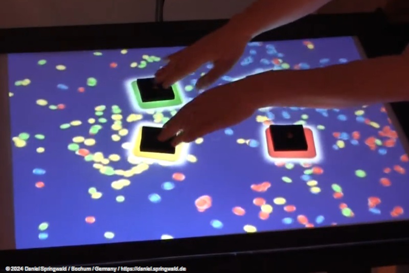
Background
Since 2006 at the latest, Multi Touch Tables have been quite well-known, as the first videos of experimental projects have appeared on the Internet.
Since then, numerous commercial providers have also taken up the issue. The best-known provider is certainly Microsoft with its Surface project
While the purchase of such a commercial product currently accounts for about 10,000 $ However, a working Multi Touch Table can also be made for less than 500 €.
This article tries to document the creation of such a low-cost Multi Touch Table in as much detail as possible. The text is not to be understood as building instructions. Any use of this information is at your own risk and risk. In particular - but not exclusively - the removal of the IR filter of the webcam used carries the risk of damage or even defect of the camera if it is not carried out properly.
How does a Multi Touch Table work?
The functionality of a multi-touch table is actually very simple - the secret actually lies only in the optical behavior of a thick acrylic glass pane:
Infrared light is beamed onto the acrylic glass pane from the side.
Due to the effect of total reflection, the light cannot leave the acrylic glass pane through the glass surface. However, if the glass surface is touched, this prevents total reflection at this point. Scattered light is generated there, which can leave the acrylic glass.
Total reflection and stray light with multi-touch table:
If you film the disc from below with an infrared camera, the areas where the fingers touch the pane will glow. By evaluating the camera image, these areas can be isolated and thus software events can be generated similar to one or more mouse pointers.
The Infrared Camera
The camera for the Multi Touch Table must only receive infrared light. However, most webcams are optimized for the normally visible range. In addition, they almost always contain an infrared filter that filters out the light in the IR range.
Of course, you can also buy digital video cameras, which have the opposite behavior and thus only record light in the IR range. While a normal webcam can be obtained for less than 100,-, the price for an IR camera is usually much higher.
(For the avoidance of doubt: IR camera does not mean not thermal imaging camera. These usually cost several thousand euros. This is just a matter of making the normal IR range visible.)
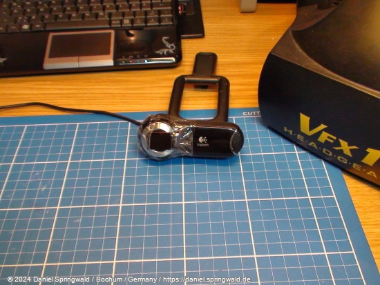
For the best possible quality of the camera image, a Logitech QuickCam Pro 9000 webcam is used as a basis. It has 2 megapixels and Carl Zeiss optics with autofocus, which leads to very good and sharp results.
The webcam becomes an infrared camera
The webcam is currently still filtering out IR light and recording normal light. However, the opposite is desired. Therefore, the IR filter contained in the camera must first be removed. A filter is then attached, which only allows IR light to pass through.
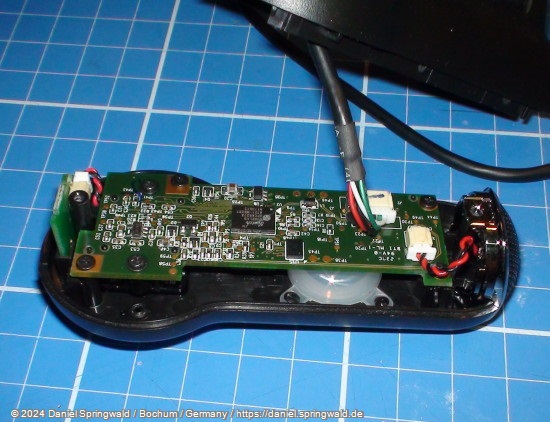
To remove the IR filter, the webcam must be opened:
Now the lens and autofocus are removed. To do this, the solder of the solder points (see arrows) with which the autofocus is connected must first be removed.
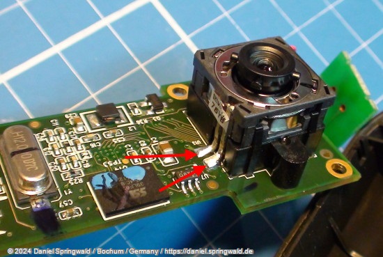
The image sensor remains on the board. Like all optical components of the camera, it should not be touched and should not be exposed to dust or dirt.
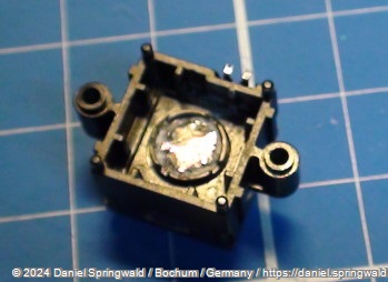
In the assumed autofocus, you can already see the infrared filter on the inside. It shimmers slightly red when tilted against the light.
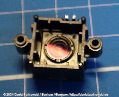
This filter must now be removed. Unfortunately, it is very well glued in and the glass is still very brittle. A simple removal in one piece is therefore almost impossible. When prying them out, safety goggles are highly recommended, as the smallest glass splinters fly around. In the meantime, the IR filter looks very scratched and broken:
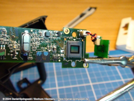
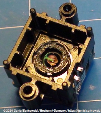
Eventually, however, the filter is removed, leaving the lens underneath exposed.
Now all you have to do is reassemble the webcam.
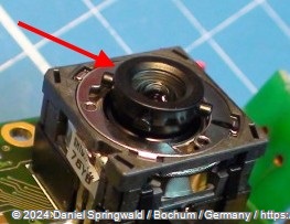
However, it is likely that the autofocus was adjusted when the IR filter was pryed out. Before finally screwing the housing together, the camera should therefore be connected to a PC. By turning the autofocus wheel (see arrow) you can recalibrate the autofocus.
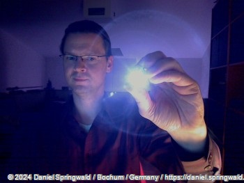
If everything went well, the webcam can now also detect infrared light. With a normal IR LED, it should already look like this:
Now the camera can also see infrared light - but normal light is also captured. To get rid of this, a filter has to be attached, which is only permeable to IR light. These filters are available in photo shops for about 30-40 €.
If you want it cheaper, you can also use an exposed photo negative. This must be exposed to the maximum, i.e. it must be completely black and opaque as a negative. Fortunately, such an exposed negative has the property that it is still permeable to IR light. If you take two to three layers of this negative on top of each other, you already have a cheap filter. The quality is not as perfect as a real photo filter, but it should be enough for first attempts.
If you still have a Wiimote left, you can also use the small black plastic mask that covers the built-in camera at the front. Since the Wiimote's camera is also only supposed to see IR light, this plastic cover is also a suitable filter:
The Infrared LED Strips
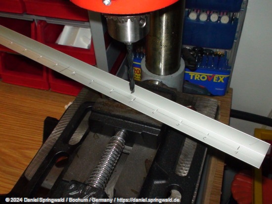
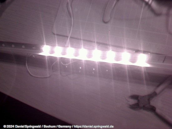
Infrared light-emitting diodes are used to illuminate the acrylic glass pane with infrared light. For uniform illumination and positioning, it is recommended to mount in a strip:
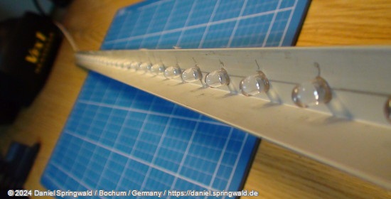
In the project presented here, a total of 112 IR LEDs are used at a distance of 1.5cm for two strips of 80cm in length.
If you use IR LEDs with 1.5 volts, you can connect 8 pieces without resistance to 12 volts in series and thus easily operate them with a normal (PC) power supply.
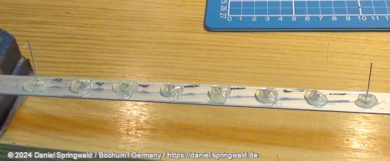
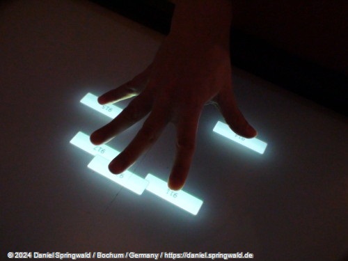
To test the wiring, you need the modified webcam, as the infrared light of the LEDs is not visible to the naked eye.
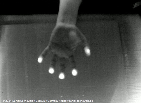
A first test with a 5mm acrylic disc already brings promising results. In the final version, an 8mm lens is used, which reduces the stray light that is still present here. But you can already see the see stray light that occurs (and is desired) at the points of contact of the fingers:
The Projection Screen
In addition to the acrylic disc for touch detection, a projection screen for computer graphics is of course also required. This must be matted accordingly so that the projected image is also visible.
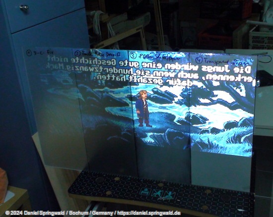
In order to find out the best surface, some experiments were carried out:
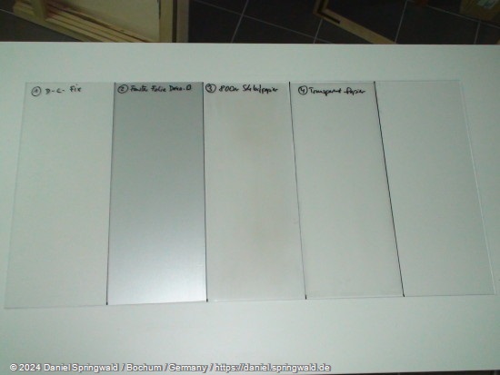
- D-C-Fix transparent
- Window film
- Matted with 800 grit sandpaper
- Glued with tracing paper
The projection screen must display the graphic well. At the same time, however, the infrared stray light from the acrylic pane above must also be allowed to pass through well and as sharply as possible. This is the only way the modified webcam can capture the touches of the fingers.
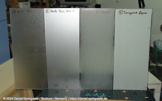
The tests showed that the surfaces 1st and 4th excrete directly: 1. is too transparent and scatters the projected light too much. 4. The IR light does not pass through sufficiently enough. All that remains is frosted window film and treating the surface with 800 grit sandpaper.
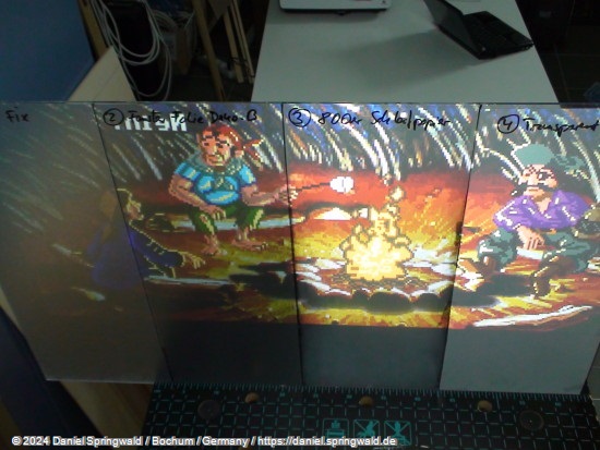
First test of the surfaces using a projector
The Hardware
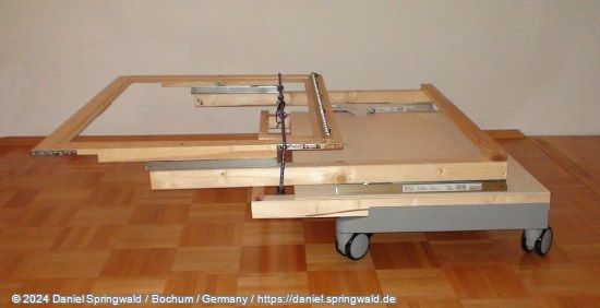
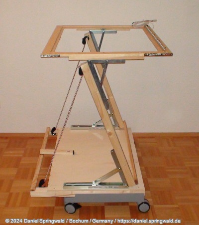
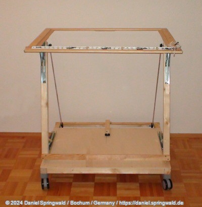
In order to arrange all components of the MultiTouchTable, an appropriate design is required. Wood is chosen as the material here. The table is collapsible and can therefore be carried by one person and transported in the trunk of a car.
When folded:
When unfolded from the side:
When unfolded from the front:
When assembled with the projection screen inserted:
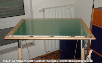
The TouchTable in working order. On the projection screen is now the acrylic glass pane:
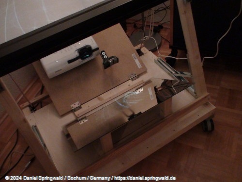
The projector and the IR webcam are deflected together by mirror:
The Software
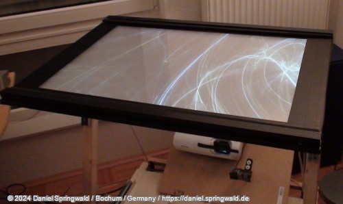
A first test software created in C# works flawlessly - including touchscreen calibration. In the first test, a WPF button is displayed under each finger:
The FireTouch Framework
To improve the reusability of the MultiTouch software, the FireTouch Framework was created. It is completely programmed in managed C# code and provides numerous components from the detection of webcam streams to WPF controls and e.g. a multi-touch canvas.
The FireTouch framework has been completely redeveloped and is therefore not based on existing libraries such as touchlib. The reason for this is that the previous libraries are mainly built in unmanaged code such as C++ and thus could crash the dotnet application in the event of an error. FireTouch, on the other hand, generates correct dotnet exceptions in case of errors, which can be handled cleanly.
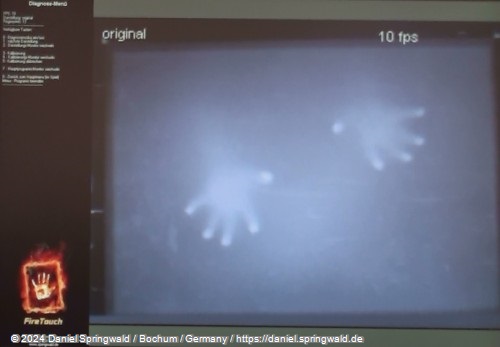
In order to be able to optimally adjust the optics and webcam, the FireTouch framework offers a diagnostic mode with different views:
Raw Mode - shows the image as it is delivered by the webcam
Bright areas - shows the image adjusted for static areas and taking into account uneven illumination of the area by the IR LEDs
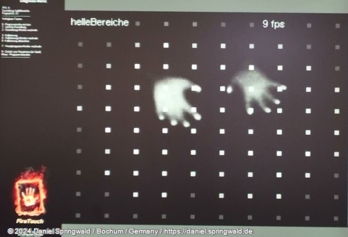 )
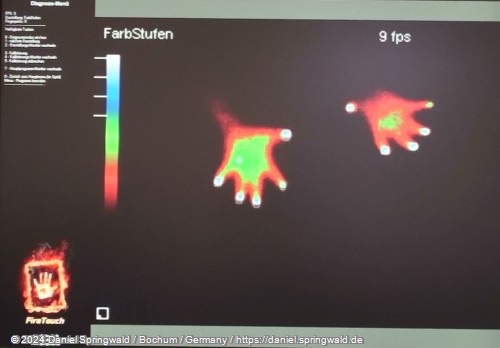
)Color visualization - the distance of the fingers from the glass pane is shown in colors: white lies directly on the pane. From blue to green to red, the distance then continues to increase until the distant areas are shown in black. In addition, fingers that have already been recognized are marked by white rectangles.
An overview of the different debug views:
A small demo application:
Object Detection
The framework now also supports the detection of objects that lie on the projection surface.
For this purpose, barcode-like markings are placed under the objects. These can then be distinguished from the applied fingers in the webcam image and evaluated.
The detected information also includes the rotation of the detected object.
An example of detecting four objects: