 Daniel
 deutsche Version anzeigen
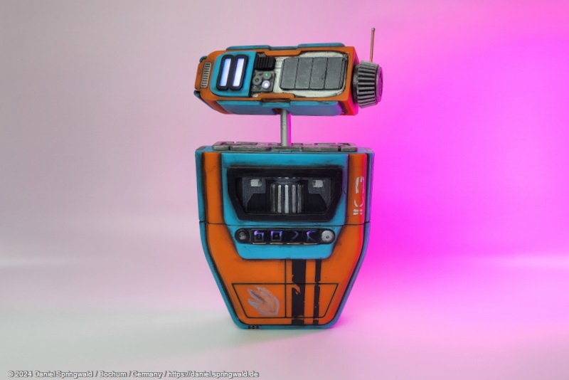
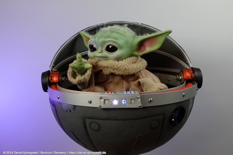
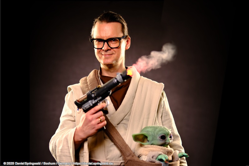
In the meantime, I'm apparently caught up in😉 the Star Wars universe: After my last two animatronic characters each had a Grogu, I have now ventured into another Star Wars character: A PIP repair droid from the series "The Acolyte".
This time, fortunately, I didn't come up with the idea three years after the hype, but discovered the character for myself in the first weeks of the series "The Acolyte" being broadcast.
A first video of my finished, animatronic PIP can be seen here:
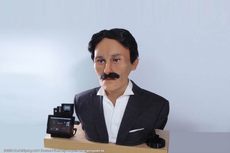
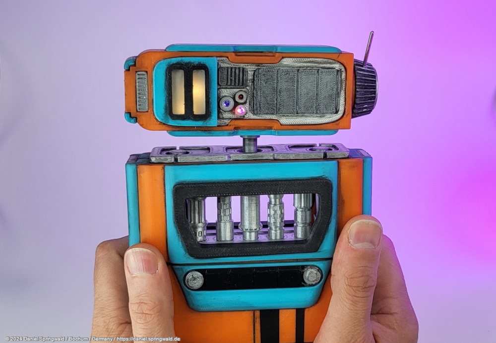
Static Size and Color Double
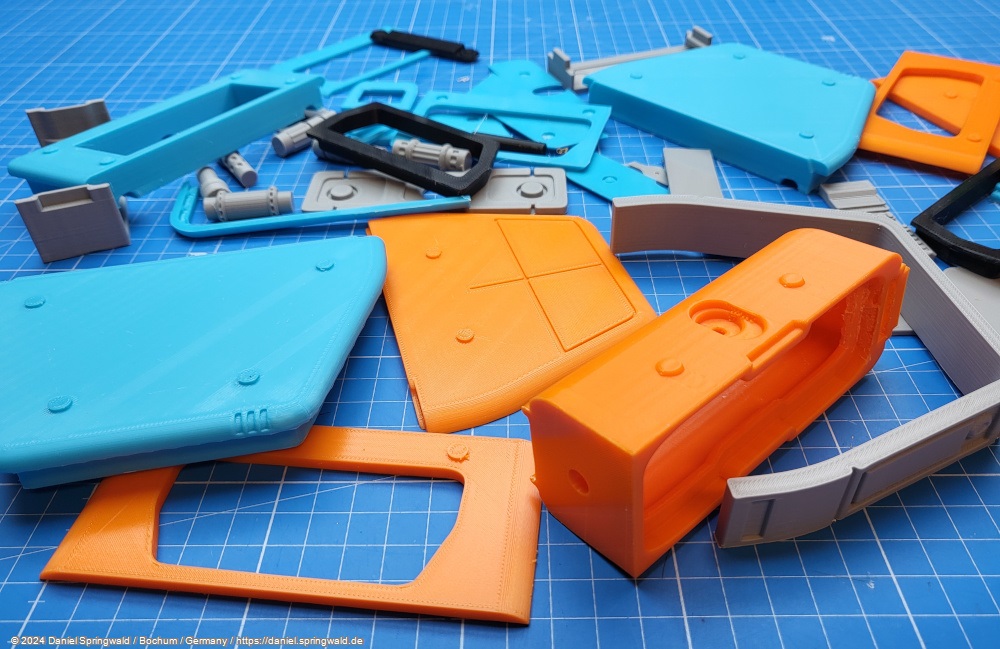
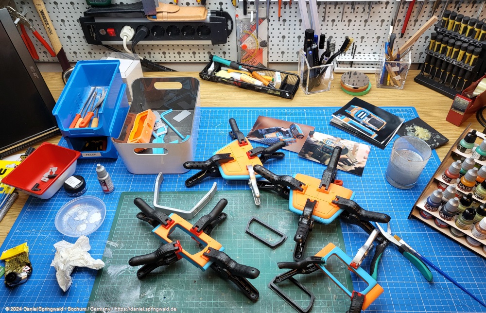
This time, the first thing I did was build a static dummy to test and experiment with the size and colors of the droid. In particular, the question of how much mechanics can fit into the body is sometimes difficult to answer on the computer alone.
Assembling the dummy:
Construction
As with the Grogu I used a 3D printer again to make the parts for the droid. I acquired the basic 3D model from the 3D artist NerdRebelArt and modified it accordingly.
Actually, only the outer shape remains - inside everything has been supplemented by mechanics and holes, e.g. for screws and speakers.
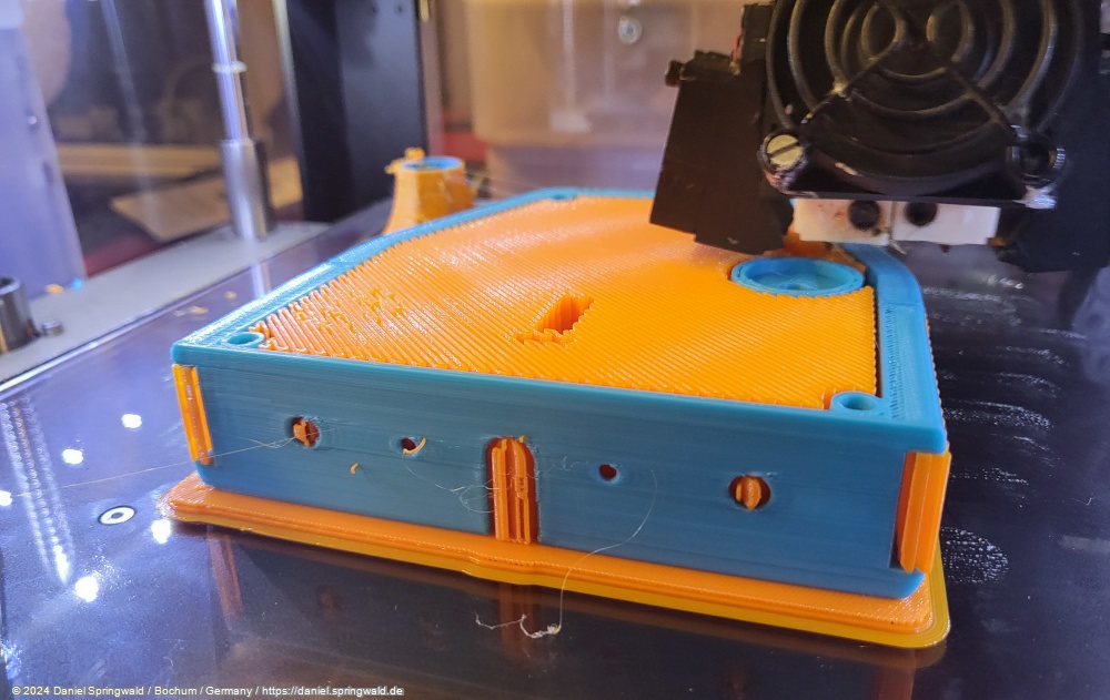
Fortunately, my 3D printer can print with several colors at the same time, so I was able to print the droid's orange and blue colors directly. This saves me the later painting or gluing together of several parts.
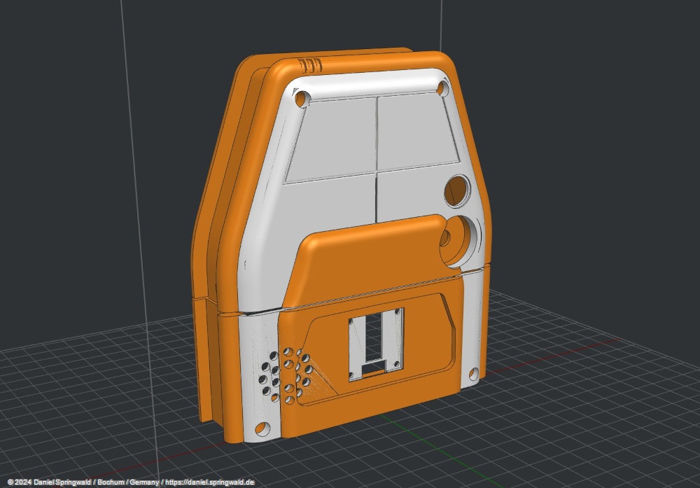
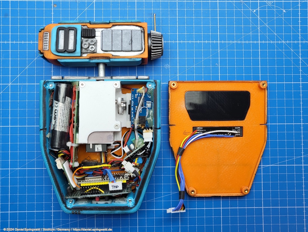
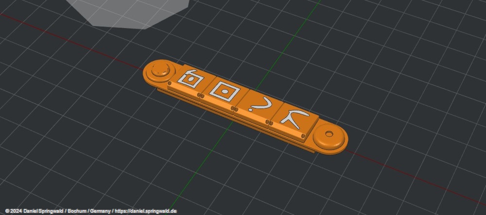
Body
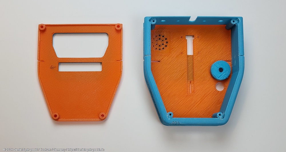
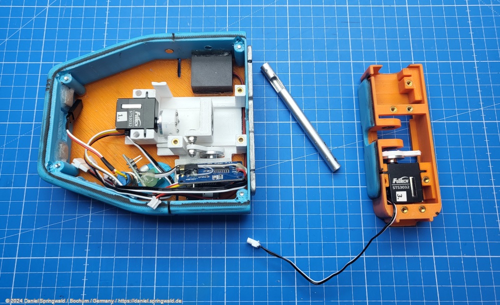
I divided the droid's body into two parts: The primary body, which contains most of the components, and a front panel, which only carries the keypad including RGB LEDs. Both are held together with 3mm screws and welded-in threaded inserts.
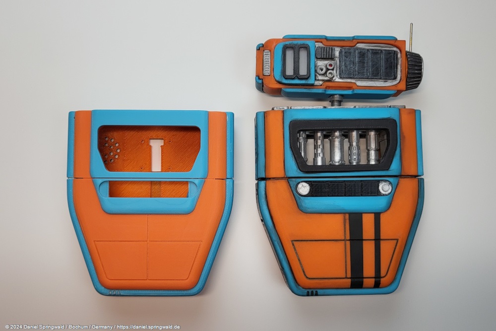
For the right "used look", the 3D printed parts still have to be sanded and aged. To do this, I applied thin black paint to all the recesses with a brush and then roughly wiped it off again. This will leave the paint only in the recesses and make the droid look "worn". A few added scratches and scuffs complete the picture.
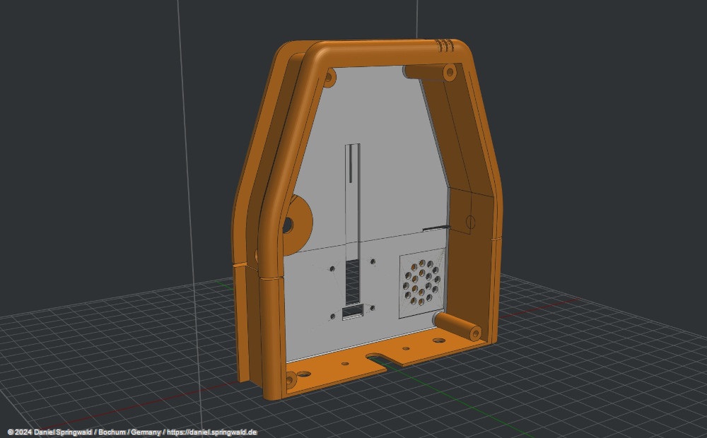
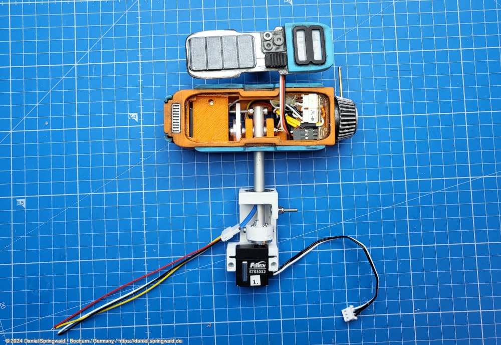
There is not a single cm³ left in the body - everything is crammed with electronics and mechanics.
These are in detail:
- An ESP32 that takes control
- YX5300 UART Serial MP3 Player Module that plays the sounds
- Mini PAM8403 Stereo Amplifier , which amplifies the sounds
- 8 Ohm 3 Watt Speaker , which reproduces the sounds
- An uninterrupted charging module that charges the battery
- 18650 Li-ion battery supplying the voltage
- Switch to turn the droid on and off
- RGB LEDs and buttons
- Spring Contacts for Power Supply
- Mechanics for the servos
- Servos for the neck movements left/right and up/down
Head
Unfortunately, there is also no space left in the head, otherwise I would have liked to have installed a small pump so that PIP can spray liquids from its antenna as in the series. But I would have had to sacrifice the movement of the ear, which can be used more often and more sensibly in comparison. I had also prepared a small mechanism to spray sparks, but unfortunately I couldn't find a place for it.
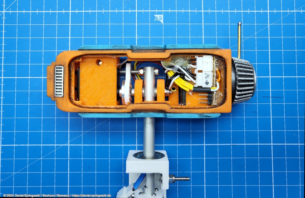
In total, the following are built into the head:
- Servo for the rotation of the ear
- Servo for the tilt of the head up/down
- RGB LEDs for the "eyes"
- Mechanism for tilting the head with ball bearings and cable routing
Mechanics
The PIP droid has 4 servos and is responsible for the following movements:
- Turn head left/right
- Extend/retract neck
- Tilt your head up/down
- Rotate the left "ear"
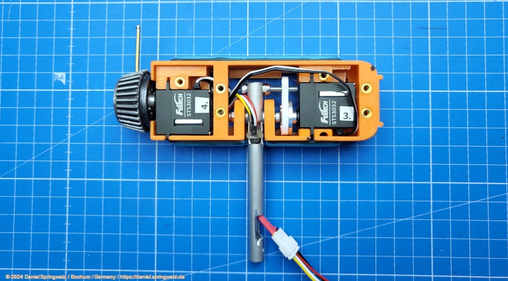
I used serial servos for this, as they can be wired in a star shape and so only one cable for both servos leads to the controller through the thin neck. I first used Feetech SCS2332 Servos as the type, but later switched to the identical model STS3032, because the STS variant also supports acceleration and so the movements seem smoother.
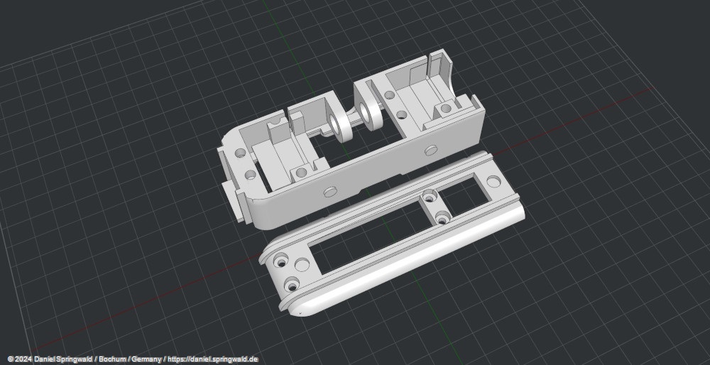
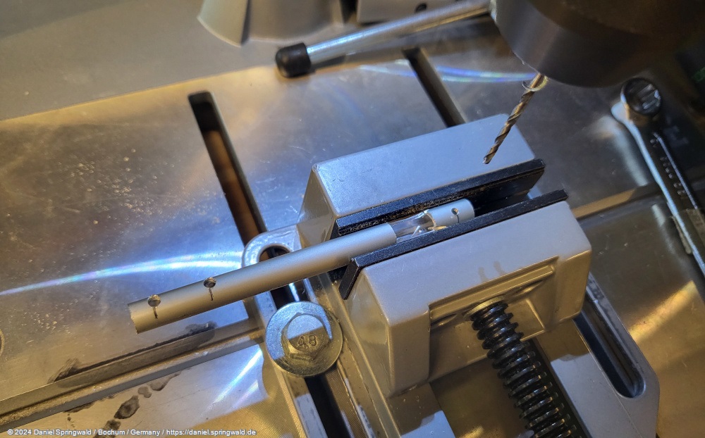
The neck consists of an aluminum rod that is guided in a 3D-printed housing. There are two ball bearings in the head that guide the rod and another ball bearing in the body.
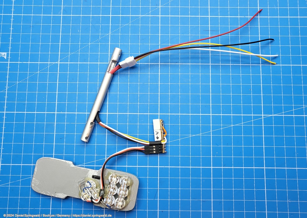
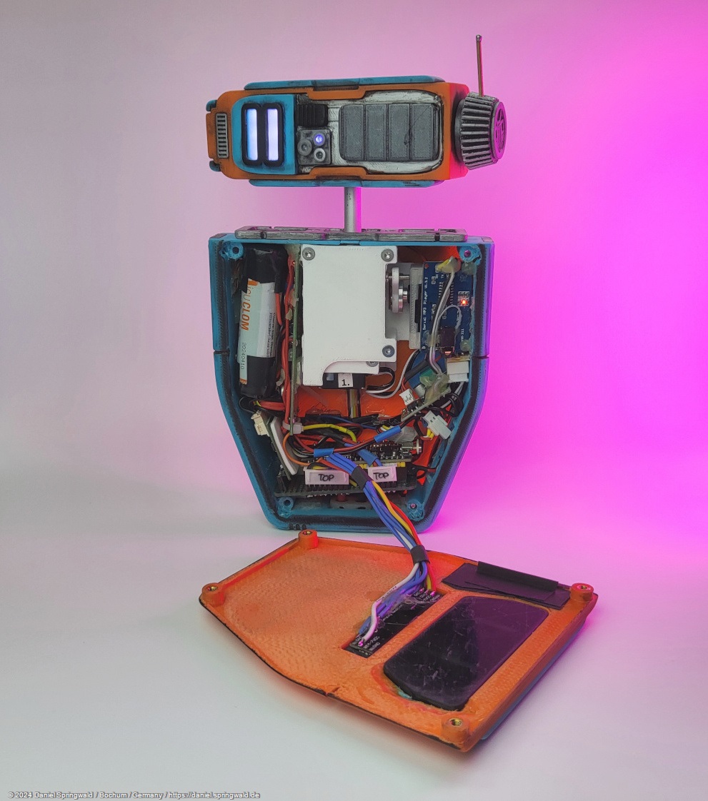
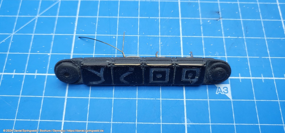
Key field
In front of the PIP droid sits a keypad consisting of four buttons. I would have liked to use a button that you can press correctly. But after subtracting the mechanics and the electronics, I have too little space in the belly of the droid if I also want to illuminate the keys. That's why I decided to make the buttons react to touch. Fortunately, the ESP32 already has touch pins that I can use for this.
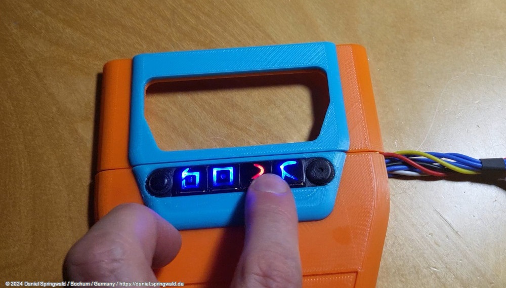
Visually, this is noticeable by the fact that a thin wire is installed in front of each key.
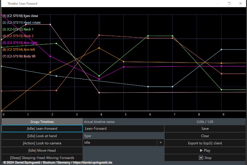
Software
As software for controlling the PIP, I use (as with the Grogu) my open source software Animatronic WorkBench.
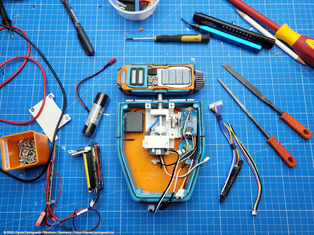
Electronic components
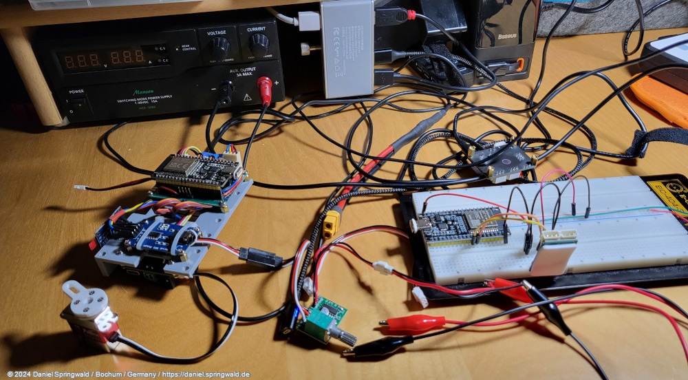
Of course, there is a lot of electronics in the PIP. Before installation, I tested and programmed the components on a breadboard.
Finding a small but powerful speaker was not easy. In the end, I chose this 8 ohm 3 watt speaker that fits in the droid's head.
As an MP3 player, I have (as with the Grogu uses a YX5300 UART Serial MP3 Player Module . This can be controlled via a serial interface and plays MP3 files from a micro SD card. This time, too, a Mini PAM8403 Stereo Amplifier serves as an amplifier.
Power supply
Inside the PIP droid is a 18650 Li-Ion battery , which is charged via an uninterrupted charging module . Therefore, all components are operated with 5 volts, although the servos could be operated with up to 6 volts and would then have more power and speed.
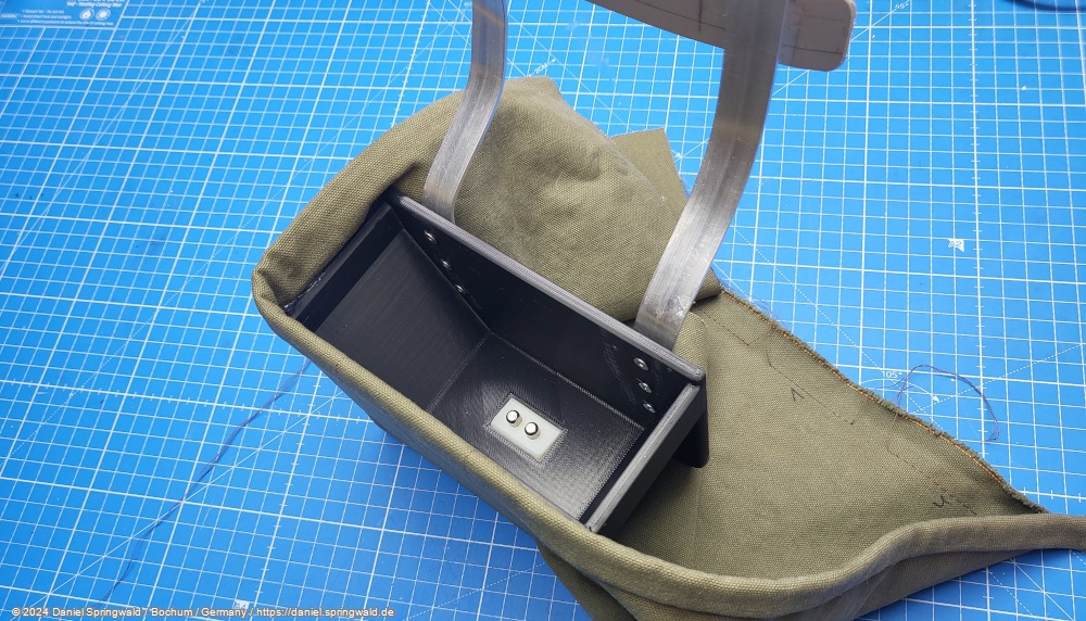
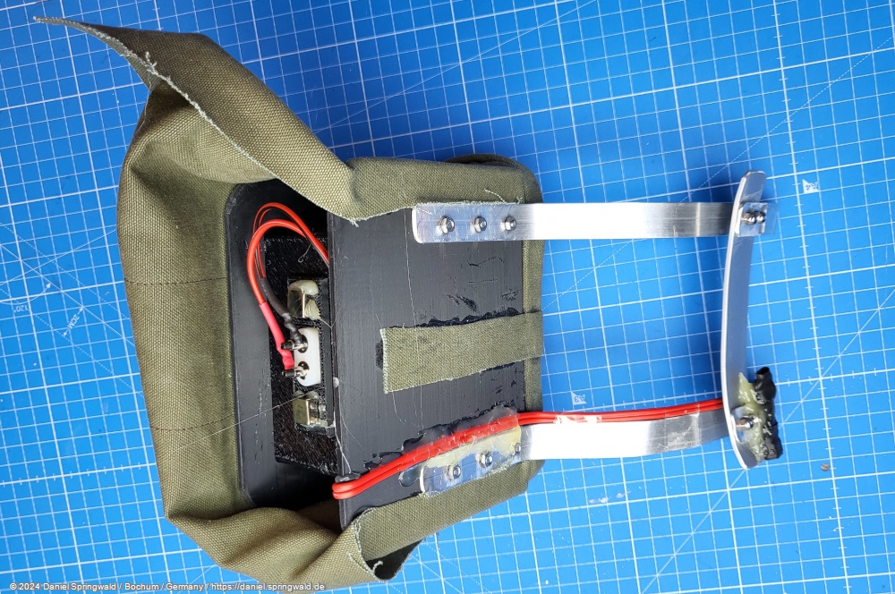
The connection for the 5 volt voltage is made via spring contacts .
Pinout of the ESP32
| ESP32 PIN | Component PIN | Component |
|---|---|---|
| GPIO17 | RXD | MP3 Player |
| GPIO16 | TXD | MP3 Player |
| GND | GND | MP3 Player |
| 5V | VCC | MP3 Player |
| GPIO18 | RXD | SCS Servos Bus |
| GPIO19 | TXD | SCS Servos Bus |
| GND | GND | SCS Servos Bus |
| GPIO22 | SLC | i²c Bus |
| GPIO21 | SDA | i²c Bus |
| 3.3V | VCC | i²c Bus |
| GND | GND | i²c Bus |
| 5V | 5V out via Schottky diode | Voltage Source |
| GND | GND | Voltage Source |
| GPIO14 | Front Pushbutton 1 | |
| GPIO27 | Front Pushbutton 2 | |
| GPIO33 | Front Pushbutton 3 | |
| GPIO32 | Front Pushbutton 4 | |
| GPIO12 | Hand Holder Back | |
| GPIO34 | per 220 Ohm to 5V Docking | Detect when docked |
Bag and docking station
For transport and storage, I sewed a bag that also serves as a docking station.
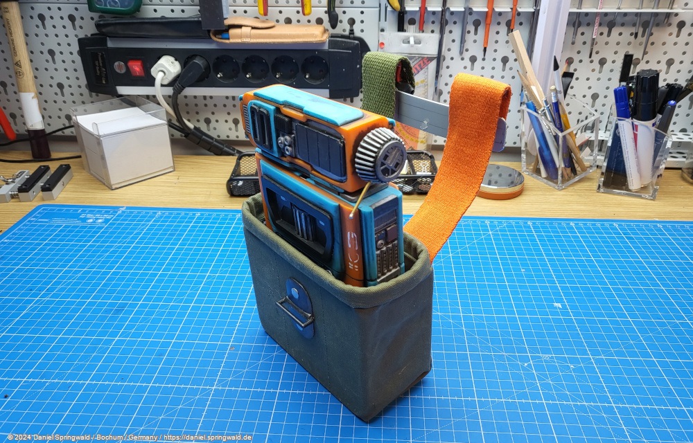
The bag has a USB port and can be operated with a power bank, which is in your trouser pocket, for example.
The docking station also has a USB port and can be operated with a power bank.
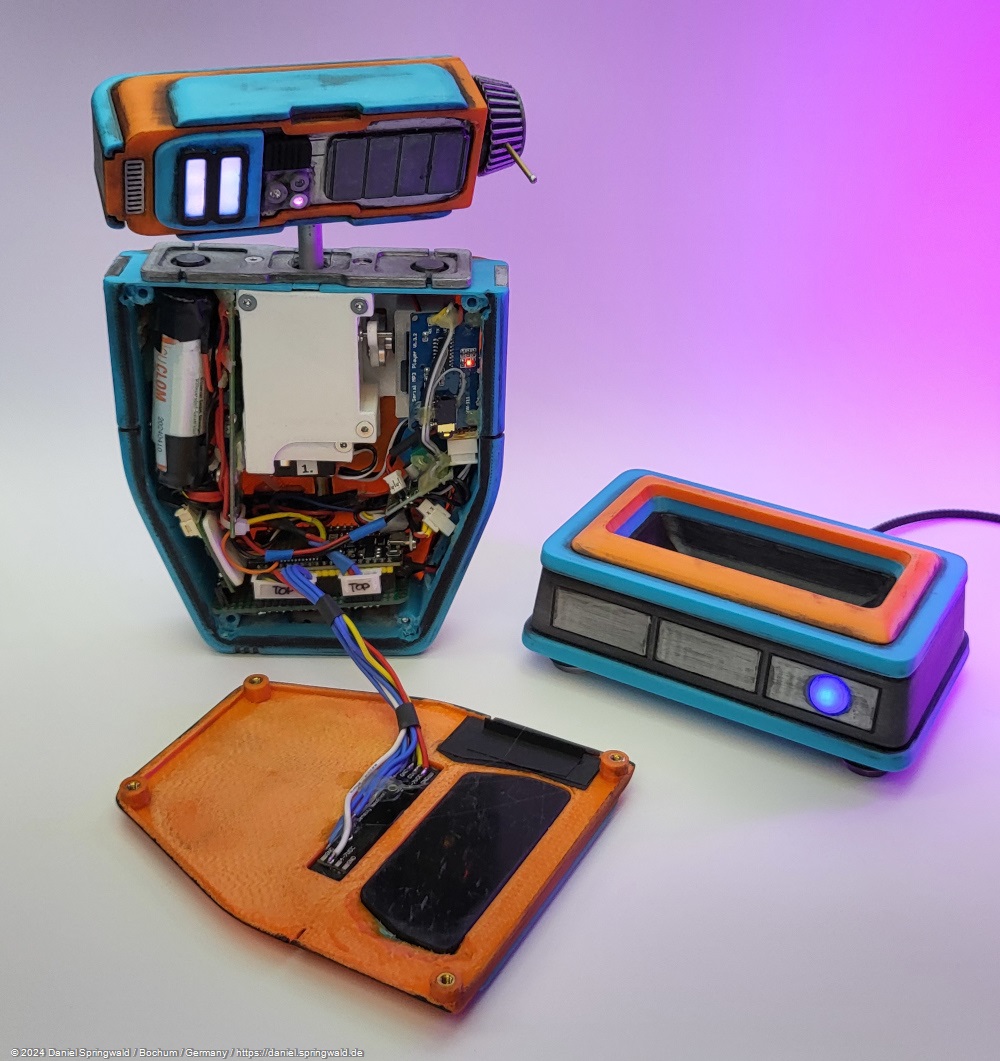
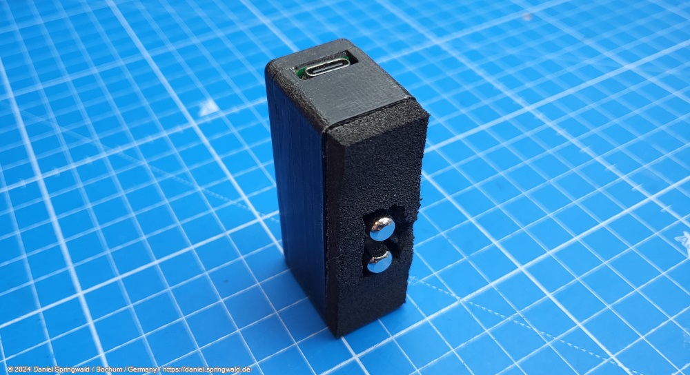
For easy charging on the go, there is also a small USB adapter that can also be magnetically snapped to the bottom of the PIP droid.
Teething troubles
The amplifier seems to overwhelm the power supply with its 3 watts when you turn up the volume. Then there is a complete voltage drop and the ESP32 restarts completely.
In the oscilloscope you can see very well that the voltage drops completely.
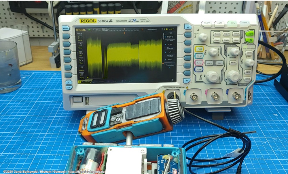
Therefore, I initially limited the amplifier to about 50% volume by means of a resistor, which is still loud enough. At even higher volumes, the small speaker has started to distort anyway.
There were also problems with the head servos at the beginning, as the head jerked slightly when turning left/right, for example. At first I thought that the servos were too weak, but in fact the problem went away directly when I held the neck a bit and made it rather heavier. My current assumption is that the motion is rocking up in a kind of wave due to an unfortunate interplay of the inertia of the head and the exact acceleration. Currently I solve this by damping the neck with a piece of foam rubber that I put in the neck and adjusting the specific rotation speed. Because a little faster or slower works fine again.